How this tool works
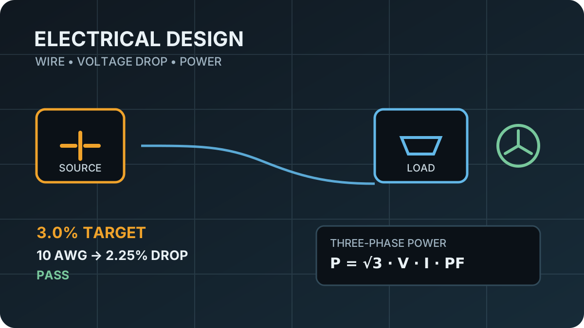
The electrical design workbench combines 32 AWG through 4/0 AWG conductor geometry, material resistivity, temperature-adjusted resistance, voltage drop, I²R loss, and power calculations in one browser workspace.
Wire recommendations use both a user-selected voltage-drop target and a clearly labeled current-density screening limit instead of presenting a generic current chart as code-approved ampacity.
The shared responsive workbench shell introduced with this tool is intended for later use by the Control System Simulator, Electronics Design Center, and DIY Power System Designer.
Method and assumptions
The conductor engine calculates gauge diameter and cross-sectional area from the AWG geometric progression, converts material resistivity into resistance per unit length, applies the selected temperature coefficient, and then evaluates the appropriate DC, single-phase, or balanced three-phase voltage-drop relationship.
Recommendations are intentionally split into two independent screens: a user-selected maximum voltage-drop percentage and a user-selected current-density ceiling. The result is not labeled code-compliant ampacity because code rules depend on installation details that are outside this first-principles model.
Assumptions
- Conductor geometry follows the American Wire Gauge progression and resistance is calculated from bulk material resistivity.
- AC voltage-drop calculations are steady-state engineering estimates. Cable reactance is user-entered because it depends on conductor geometry and installation.
- Three-phase power calculations assume a balanced system and use line-to-line voltage with line current.