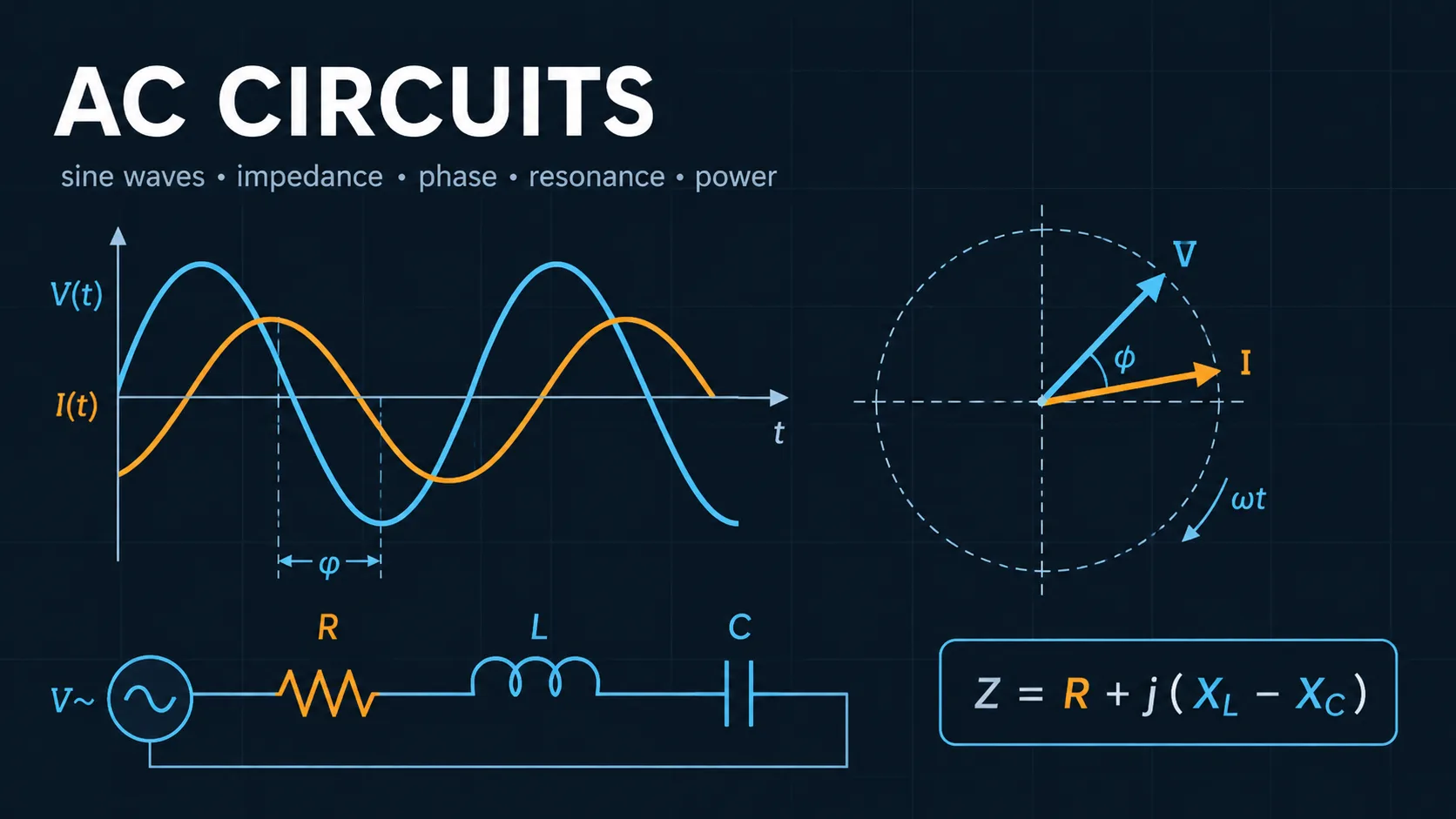
Tuning a series RLC branch to unity power factor
A 230 V single-phase branch feeds a 12 Ω resistive load through a 25 mH reactor and a 47 µF capacitor. At the 50 Hz supply frequency the branch draws heavy leading reactive current, so the question is what the branch actually does at 50 Hz and what happens if the source is driven at the resonant frequency instead.
Interpretation: This is why series resonance is a hazard as much as a design tool. The branch looks harmless at the supply frequency, yet a harmonic or drive near 147 Hz would push it to over 19 A with nothing but the 12 Ω resistor limiting it. The quality factor Q = (1/R)√(L/C) = 1.922 gives a −3 dB bandwidth of f₀/Q ≈ 76.4 Hz, which is wide enough that ordinary supply harmonics fall inside it. Check the resonant frequency of any power-factor correction branch against the harmonic spectrum it will actually see.