Browser-local interactive workspace
Interactive workspace initializes in your browser. Engineering method, assumptions, validation, and references are available below.

Engineering reference

Introductory Circuits: theory, method, and sources

This electrical engineering workspace publishes 10 governing equations, 5 stated assumptions, 3 documented boundaries, and 3 sources so the numbers it returns can be checked rather than taken on trust.

Calculations run locallyCalculation & source methodology

How this tool works

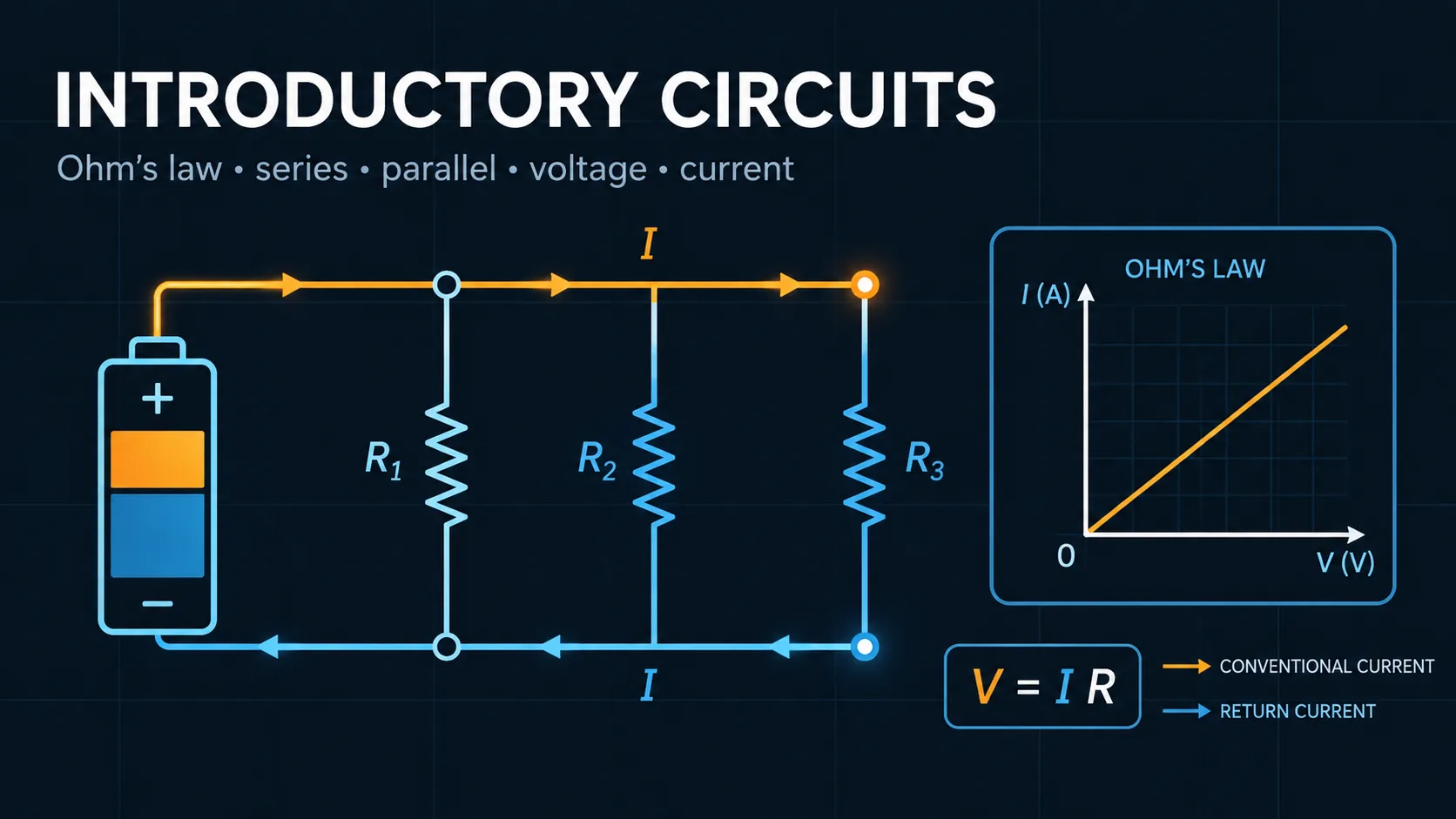
Fifteen guided modules connect basic electrical quantities to complete DC and introductory AC circuit behavior.

Each module states the engineering question, shows the governing relationship, calculates live results, and provides a schematic or unit-labeled graph.

Inputs, restored state, list lengths, graph samples, and numerical ranges are bounded before calculations and drawing.

Calculators and topics covered

  • circuits
  • ohms law
  • kirchhoff laws
  • resistors
  • capacitors
  • inductors
  • AC circuits
  • voltage
  • current
  • resistance
  • power
  • series circuit
  • parallel circuit
  • voltage divider

Core equations

V=IRV = IRP=VI=I2R=V2RP = VI = I^{2} R = \frac{V^{2}}{R}Rseries=RR_{\mathrm{series}} = \sum R1Rparallel=(1R)\frac{1}{R_{\mathrm{parallel}}} = \sum \left(\frac{1}{R}\right)Inode=0\sum I_{\mathrm{node}} = 0Vloop=0\sum V_{\mathrm{loop}} = 0VC(t)=Vf+(V0Vf)etRCV_{C} \left(t\right) = V_{f} + \left(V_{0} - V_{f}\right) e^{\frac{- t}{RC}}IL(t)=If+(I0If)etRLI_{L} \left(t\right) = I_{f} + \left(I_{0} - I_{f}\right) e^{\frac{- tR}{L}}Z=R+j(ωL1ωC)Z = R + j \left(\omega L \frac{- 1}{\omega C}\right)f0=12πLCf_{0} = \frac{1}{2 \pi \sqrt{LC}}

Method and assumptions

Assumptions

  • Wires and ideal sources have zero internal impedance unless an equivalent resistance is explicitly provided.
  • Resistors are linear and temperature independent.
  • RC and RL modules use ideal first-order lumped components.
  • AC modules use sinusoidal steady-state RMS quantities and ideal components.
  • The resistor color-code module uses the standard four-band interpretation.

Limitations and design boundaries

  • This is an educational analysis tool, not a substitute for electrical safety procedures, component datasheets, SPICE simulation, laboratory measurement, or professional design review.
  • The workbench does not model parasitics, tolerance distributions, temperature rise, saturation, dielectric breakdown, source current limits, transmission-line effects, semiconductor nonlinearities, or electromagnetic interference.
  • High-voltage and high-current circuits can cause severe injury, fire, and equipment damage even when the arithmetic is correct.

Sources and references

Primary sources are preferred for ratings, standards, manufacturer data, and externally defined constants.

Source policy
  • Alexander and Sadiku, Fundamentals of Electric CircuitsIntroductory DC, transient, and sinusoidal circuit-analysis relationships.
  • Nilsson and Riedel, Electric CircuitsKirchhoff laws, equivalent circuits, first-order response, and AC analysis.
  • IEC 60062Reference convention for resistor color marking.