Voltage direction, timing, and power balance
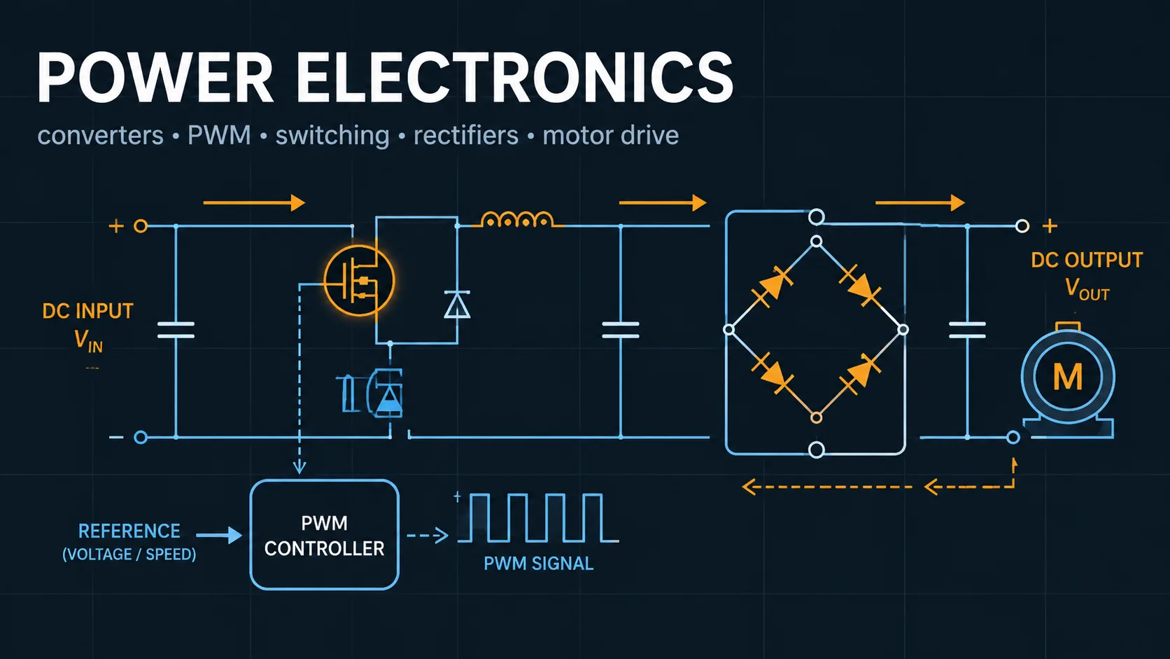
A buck converter reduces voltage; a boost converter raises it. Entering a buck target above its input, or a boost target below it, does not become valid by clipping the duty cycle. This workbench rejects those combinations and explains which topology can support the requested direction. Ideal high-duty ratios are retained, with a warning that actual minimum off-time, switch loss, and control limits may make them impractical.
For buck, boost, and inverting buck-boost, the triangular ripple estimate assumes continuous conduction. If the calculated current valley reaches zero, the conduction mode changes and the CCM equation set no longer predicts a diode-based DCM operating point. The displayed waveform is then an extrapolation used to identify the model boundary. Efficiency is an entered power-budget assumption, not a prediction of a particular controller or semiconductor.