Analog Electronics Workbench
Study op-amp feedback, summing and differential stages, active filters, comparators, transistor amplifiers, instrumentation amplifiers, and oscillators.
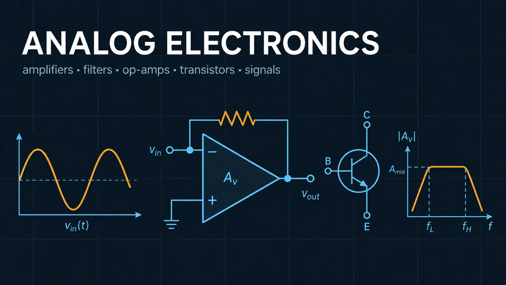
Engineering reference
Analog Electronics: theory, method, and sources
This electrical engineering workspace publishes 5 governing equations, 3 stated assumptions, 1 documented boundary, and 2 sources so the numbers it returns can be checked rather than taken on trust.
How this tool works
Twelve guided modules connect ideal feedback rules to practical gain, clipping, frequency response, hysteresis, transistor degeneration, and oscillation conditions.
All quantitative plots include axis quantities and units such as volts, amperes, ohms, hertz, milliseconds, decibels, and degrees.
State normalization and fixed graph sampling prevent extreme values from destabilizing the browser.
Calculators and topics covered
- analog electronics
- op amps
- active filters
- amplifiers
- comparators
- oscillators
- inverting amplifier
- non-inverting amplifier
- summing amplifier
- difference amplifier
- integrator
- differentiator
- Schmitt trigger
- Bode plot
Core equations
Method and assumptions
Assumptions
- Operational amplifiers are ideal except for user-selected output rails.
- Transistor stages use small-signal linear models at 300 K.
- Filters use ideal lumped components and normalized transfer functions.
Limitations and design boundaries
- Not a substitute for SPICE, gain-bandwidth and slew-rate analysis, noise calculations, stability compensation, offset and bias-current analysis, distortion measurement, or laboratory validation.
Sources and references
Primary sources are preferred for ratings, standards, manufacturer data, and externally defined constants.
- Sedra and Smith, Microelectronic CircuitsOperational amplifiers, transistor amplifiers, and feedback.
- Sergio Franco, Design with Operational Amplifiers and Analog Integrated CircuitsPractical op-amp circuits, filters, comparators, and oscillators.