Loading tool…
Loading interactive tool…

Engineering reference

Theory, method, validation, and sources

The interactive workspace is paired with its published engineering context: core equations, assumptions, design boundaries, and source references. Worked examples, validation cases, and editorial review dates are displayed only where that supporting evidence has been published for the tool.

Calculations run locallyContent reviewed August 9, 2026Calculation & source methodology

How this tool works

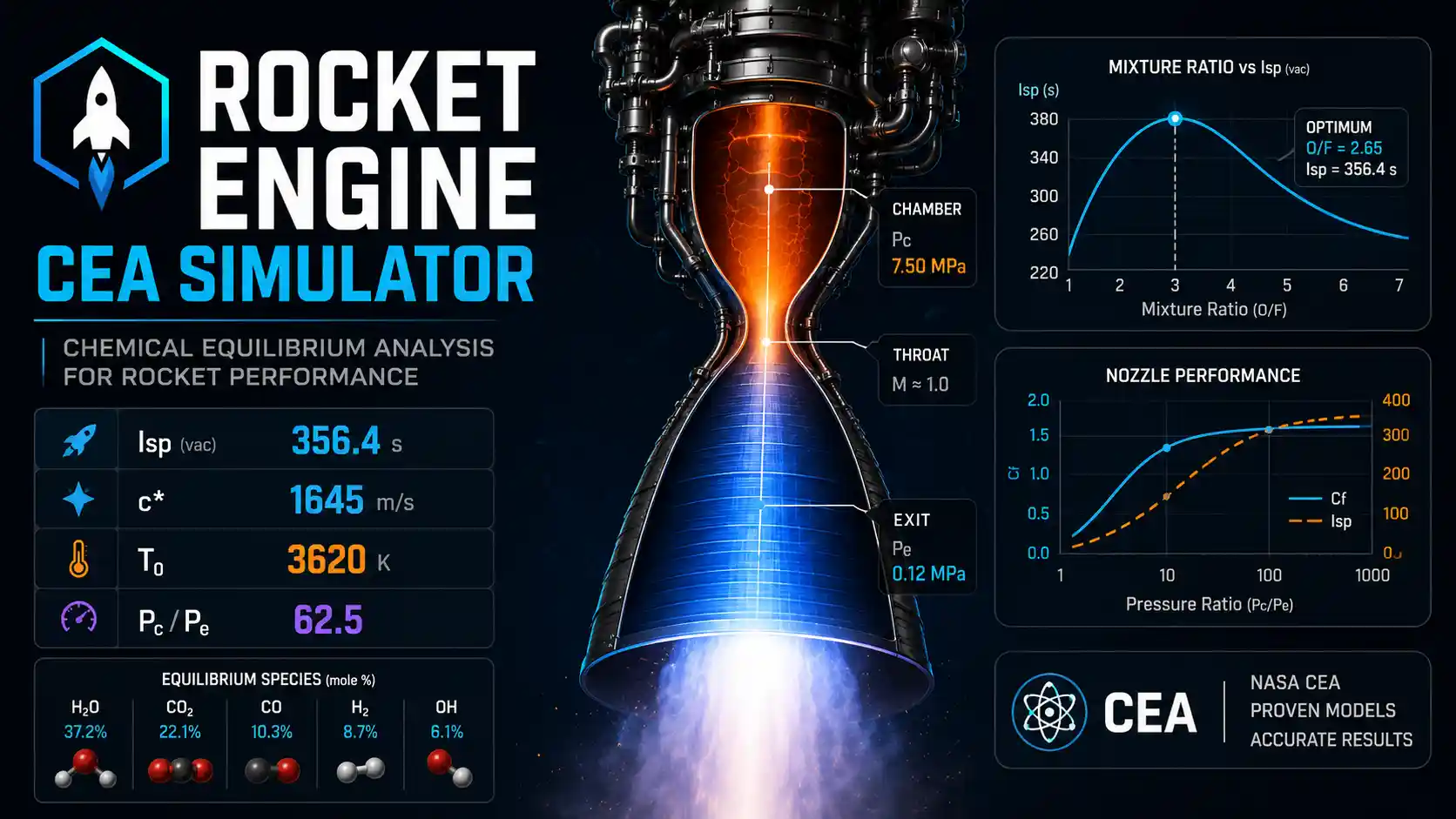
This simulator connects propellant chemistry to ideal rocket performance. Instead of asking the user to supply chamber temperature, molecular weight, or heat-capacity ratio, it solves the gas-phase equilibrium state from the reactants and then expands that state through an ideal nozzle.

It is intended for thermochemistry, propulsion coursework, and preliminary comparative studies. It does not model injector design, combustion stability, cooling, finite-rate reaction kinetics, structural loads, manufacturing, ignition systems, or propellant handling.

Engineering theory

Chemical equilibrium determines the chamber state

At fixed pressure and temperature, the stable gas composition minimizes total Gibbs free energy subject to elemental conservation. The simulator uses the element-potential formulation described by Gordon and McBride and evaluates species properties from NASA Glenn polynomial data.

The chamber temperature is not entered directly. It is found from the constant-pressure adiabatic energy balance, so mixture ratio and propellant chemistry jointly determine flame temperature, product composition, mean molar mass, and thermodynamic properties.

Ideal nozzle expansion converts chamber energy into jet velocity

The chamber is treated as a stagnation reservoir. The throat is located at maximum mass flux, and the exit state is found from the requested area ratio under steady, adiabatic, one-dimensional isentropic flow.

Shifting-equilibrium flow re-equilibrates composition as pressure and temperature fall. Frozen flow holds chamber composition fixed during expansion. Real engines generally fall between these idealized limits.

Inputs and outputs explained

Inputs

Fuel and oxidizer

Selects the reactant elemental composition, formation enthalpy, storage temperature, and density used by the equilibrium and density-impulse calculations.

Mixture ratio O/Fkg/kg

Oxidizer-to-fuel mass ratio supplied to the chamber.

The chemically stoichiometric ratio does not necessarily maximize specific impulse.
Chamber pressurebar

Stagnation pressure used for the chamber equilibrium state and nozzle expansion.

Nozzle area ratioAe/At

Exit area divided by throat area.

Ambient pressurebar

External pressure used in the thrust-coefficient pressure term.

Equilibrium model

Choose shifting-equilibrium or frozen-composition expansion where the module exposes that comparison.

Outputs

Adiabatic chamber temperatureK

Equilibrium flame temperature from the reactant enthalpy balance.

Product compositionmole fraction

Gas-phase equilibrium mole fractions at the selected chamber, throat, or exit station.

Characteristic velocity c*m/s

Combustion-performance quantity defined from chamber pressure, throat area, and mass flow.

Thrust coefficient CF

Dimensionless conversion between chamber pressure-throat-area product and ideal thrust.

Specific impulse Isps

Ideal thrust per unit propellant weight flow for the selected nozzle and ambient pressure.

Calculators and topics covered

  • rocket propulsion
  • chemical equilibrium
  • specific impulse
  • combustion
  • nozzles
  • CEA
  • chemical equilibrium with applications
  • adiabatic flame temperature
  • characteristic velocity
  • thrust coefficient
  • mixture ratio optimisation
  • shifting equilibrium
  • frozen flow
  • Gibbs free energy minimisation

Core equations

min G = Σ nⱼ μⱼ subject to Σ aᵢⱼnⱼ = bᵢμⱼ/RT = gⱼ°/RT + ln(nⱼ/n) + ln Ph(Tc) = h(reactants) at constant pressures(T, p) = s(Tc, pc) along the nozzlec* = pcAt/ṁCF = F/(pcAt)Isp = c*CF/g₀

Worked examples

LOX/LH2 reference operating point

The bundled validation documentation compares a LOX/LH2 case at O/F = 6.0 and 68.05 bar against published NASA CEA results.

Inputs
  • Fuel: LH2
  • Oxidizer: LOX
  • O/F = 6.0
  • Chamber pressure = 68.05 bar

Result: The documented tool result is approximately 3482 K chamber temperature and 2304 m/s characteristic velocity.

Interpretation: The comparison is a regression/reference check for the implemented equilibrium and thermodynamic model, not a guarantee of equal accuracy over every propellant combination or operating condition.

Common mistakes

Treating ideal Isp as delivered engine performance

The equilibrium/nozzle solution omits injector losses, boundary layers, divergence, film cooling, incomplete combustion, and other hardware effects.

Better approach: Use the result as an ideal thermochemical/nozzle reference and apply experimentally justified efficiency models separately when comparing real engines.

Using gas-only results where condensed products matter

Fuel-rich hydrocarbon or metallized cases can form condensed species that materially alter equilibrium and performance.

Better approach: Treat those operating points as outside this tool's stated validity and use a solver that includes the relevant condensed phases.

Assuming shifting and frozen flow are interchangeable

Composition can continue changing during expansion in the shifting model, while frozen flow locks chamber composition.

Better approach: Use both as idealized bounds when the difference is important and avoid implying that either exactly represents finite-rate nozzle chemistry.

Method and assumptions

Select gas-phase product species whose elements are a subset of the reactant element set.

Solve chemical equilibrium by Gibbs free-energy minimization using element potentials and NASA Glenn thermodynamic polynomials.

Solve the constant-pressure adiabatic chamber temperature from the enthalpy balance.

Locate the sonic throat by maximizing mass flux, then solve the isentropic exit state at the requested area ratio.

Derive c*, CF, Isp, station properties, and sweep curves from the converged chamber/nozzle solution.

Treat condensed products, finite-rate chemistry, heat transfer, viscous losses, and hardware-specific efficiency as outside the model.

Assumptions

  • Products are treated as a mixture of ideal gases in full chemical equilibrium at each station.
  • Only gas-phase species are considered; condensed products such as solid carbon or metal oxides are not included, so heavily fuel-rich hydrocarbon mixtures fall outside the model.
  • Flow through the nozzle is steady, adiabatic, one-dimensional, and isentropic, with the throat located at the section of maximum mass flux.
  • Shifting equilibrium assumes composition re-equilibrates instantly; frozen flow assumes it is fixed at the chamber value. Real engines fall between the two.
  • Combustion is assumed complete and the chamber is assumed to be a stagnation reservoir, so injector, mixing, residence-time, and heat-loss effects are excluded.
Limitations and design boundaries

  • This is a theoretical performance tool for education and preliminary study, not an engine-design, flight-certification, combustion-stability, cooling, or safety-analysis tool.
  • Real delivered performance is lower than the ideal values shown here because of combustion inefficiency, boundary layers, divergence losses, film cooling, and finite-rate chemistry.
  • It provides no propellant formulations, manufacturing procedures, ignition systems, or handling instructions; the propellants modelled are hazardous and several are acutely toxic.
  • The bundled species list covers C, H, O, N, F, Cl, S, and the noble gases. Metallised propellants, exotic oxidisers, and condensed-phase products are not represented.
  • Results are typically within a few percent of NASA CEA for common combinations, but this is an independent reimplementation and is not a validated substitute for CEA itself.

Validation cases

These checks document how representative calculations are cross-checked against analytic or reference results.

Validation policy

Sonic-throat consistency check

Analytic cross-check
Method
Locate the throat by maximum mass flux and independently compute Mach number at the converged throat state.
Expected
Mach number = 1 at the throat within numerical tolerance.

LOX/LH2 thermochemical reference

Reference cross-check
Method
Compare the documented O/F 6.0, 68.05 bar case with published NASA CEA reference values.
Expected
Chamber temperature and c* remain within the documented roughly 1–2% comparison range.
Observed
Current documented result: Tc ≈ 3482 K; c* ≈ 2304 m/s.

Sources and references

Primary sources are preferred for ratings, standards, manufacturer data, and externally defined constants.

Source policy
  • Gordon, S. and McBride, B.J., NASA RP-1311Computer Program for Calculation of Complex Chemical Equilibrium Compositions and Applications; the element-potential formulation used here.
  • McBride, B.J., Zehe, M.J., Gordon, S., NASA TP-2002-211556NASA Glenn coefficients for calculating thermodynamic properties of individual species.
  • NASA CEA projectThermodynamic database source, Apache-2.0 licensed. See licenses/nasa-cea/ for attribution.
  • Sutton and Biblarz, Rocket Propulsion ElementsStandard definitions of characteristic velocity, thrust coefficient, and specific impulse.

Related concepts