Flight Aerodynamics Calculators & Workbench
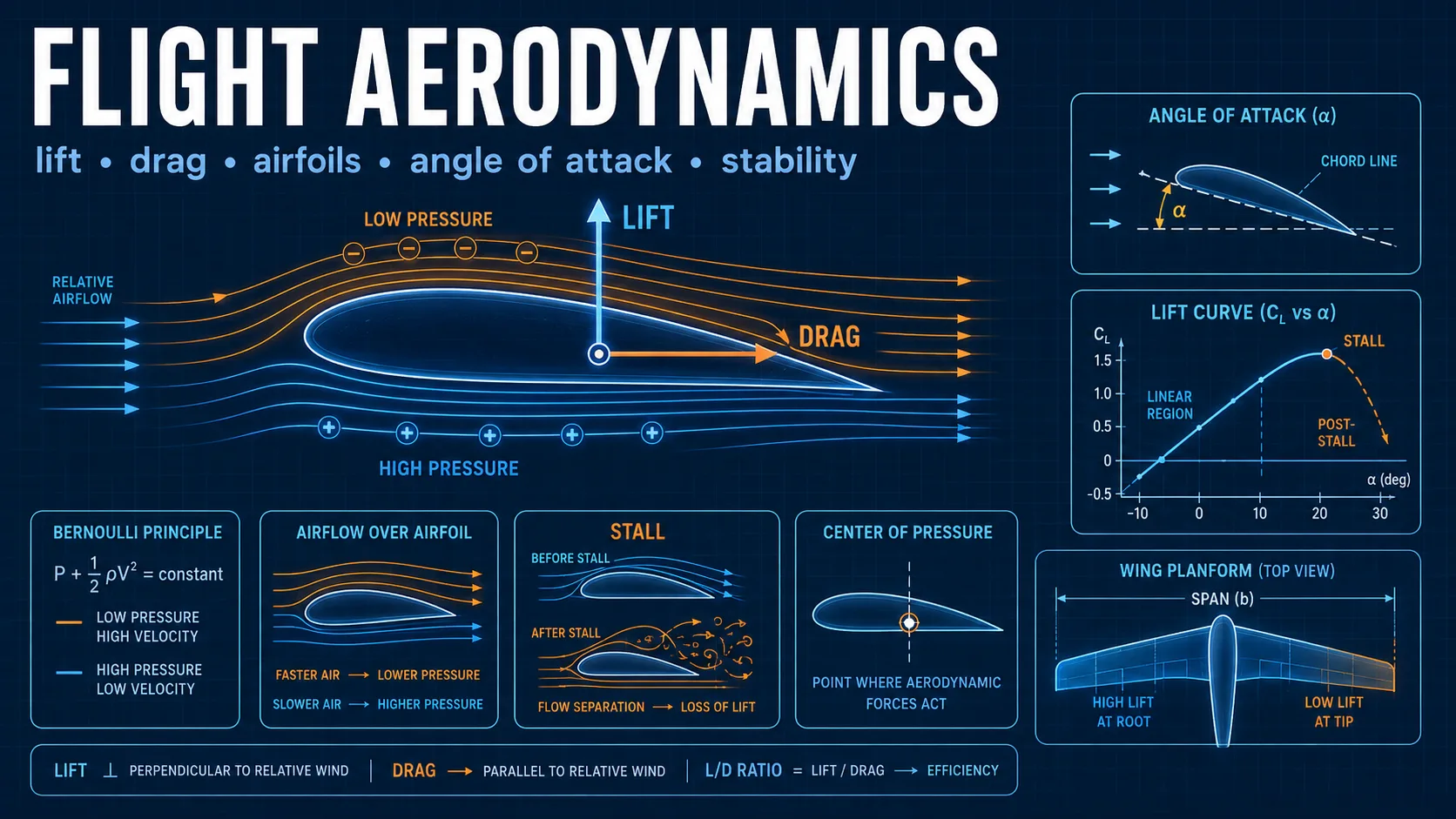
Free aerodynamics calculators for lift, drag, dynamic pressure, stall speed, wing loading, aircraft performance, atmosphere, and flight mechanics.
Engineering reference
Flight Aerodynamics: theory, method, and sources
This aerospace & rocket science workspace publishes 8 governing equations, 5 stated assumptions, 3 documented boundaries, and 3 sources so the numbers it returns can be checked rather than taken on trust.
How this tool works
Fourteen guided modules connect atmospheric properties and aerodynamic coefficients to aircraft performance and stability.
The workbench covers forces, drag polar behavior, glide, stall, level flight, climb, coordinated turns, field-length estimates, viscous scaling, compressibility, and static margin.
Every quantitative graph includes explicit units, and all inputs are bounded before calculations and drawing.
Calculators and topics covered
- aerodynamics
- flight performance
- lift
- drag
- stall
- stability
- standard atmosphere
- dynamic pressure
- drag polar
- glide ratio
- wing loading
- climb rate
- turn radius
- takeoff distance
Core equations
Method and assumptions
Assumptions
- The atmosphere is a simplified dry-air standard model through 50 km.
- The drag model is a parabolic polar with constant C_D0, aspect ratio, and Oswald efficiency.
- Level-flight, climb, turn, takeoff, and landing modules use steady or average-force approximations.
- Compressibility uses ideal-gas stagnation relations and a first-order subsonic correction.
- Static stability uses a simplified wing-tail neutral-point estimate.
Limitations and design boundaries
- The workbench is educational and is not a flight-planning, certification, dispatch, structural-load, control-law, or handling-quality tool.
- Takeoff and landing estimates omit wind, runway slope, pilot delay, flare, tire and brake limits, hydroplaning, ground effect, engine variation, and regulatory factors.
- Real aircraft analysis requires validated aerodynamic data, propulsion maps, weight and balance data, aeroelastic effects, CFD or wind-tunnel evidence, and flight test.
Sources and references
Primary sources are preferred for ratings, standards, manufacturer data, and externally defined constants.
- NASA Glenn Research CenterEducational references for lift, drag, atmosphere, Mach number, and aircraft performance.
- Anderson, Aircraft Performance and DesignStandard aerodynamic and flight-performance relationships.
- Etkin and Reid, Dynamics of FlightLongitudinal stability terminology and static-margin concepts.