Loading tool…
Loading interactive tool…

Engineering reference

Theory, method, validation, and sources

The interactive workspace is paired with its published engineering context: core equations, assumptions, design boundaries, and source references. Worked examples, validation cases, and editorial review dates are displayed only where that supporting evidence has been published for the tool.

Calculations run locallyContent reviewed August 10, 2026Calculation & source methodology

How this tool works

Visualize common crystal structures and molecular bases in a rotatable, zoomable three-dimensional projection directly in the browser.

Edit lattice constants, angles, fractional atomic coordinates, replication counts, neighbor cutoffs, and display options to turn a preset into a custom material or molecule.

Overlay a Miller plane (hkl) and a crystallographic direction [uvw], select atoms to inspect their coordinates and nearest neighbors, and export unit-cell or supercell geometry.

Engineering theory

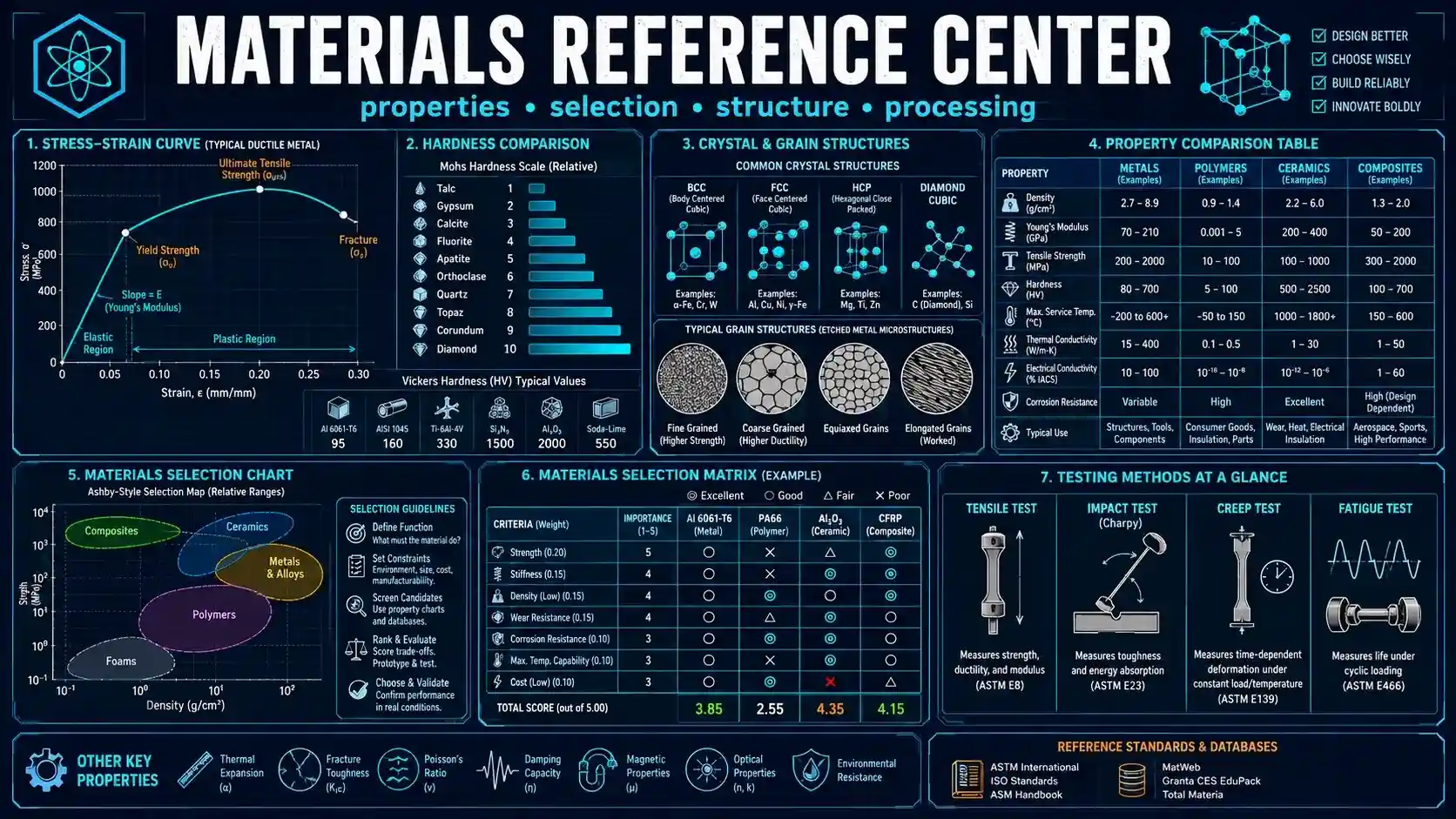
A crystal structure is a lattice plus a basis

The lattice defines the translational symmetry through three vectors a⃗, b⃗, and c⃗. The basis specifies one or more atoms or molecular sites in fractional coordinates. Replicating the basis by integer translations builds the extended crystal structure.

Conventional cells such as FCC or diamond contain several basis positions because the chosen cell emphasizes symmetry rather than minimizing the number of lattice points.

Fractional coordinates separate structure from cell dimensions

A fractional coordinate such as (1/2, 1/2, 1/2) remains at the body center even if the lattice constants or cell angles change. Cartesian positions are obtained from the linear combination x a⃗ + y b⃗ + z c⃗.

This is why the custom editor uses fractional coordinates: the same atomic basis can be explored under different lattice parameters without manually recalculating XYZ coordinates.

Miller indices describe planes; [uvw] indices describe directions

For the simplified plane drawn here, the fractional-coordinate equation is hx + ky + lz = 1. The visual overlay clips that plane to the first unit cell so the orientation can be compared with the atoms and cell edges.

A crystallographic direction [uvw] is constructed as u a⃗ + v b⃗ + w c⃗. In non-cubic cells, a plane normal and a direction with the same integer indices are not generally parallel in Cartesian space.

Inputs and outputs explained

Inputs

Lattice constantsÅ

Lengths a, b, and c of the crystallographic cell.

Cell anglesdegrees

Angles α, β, and γ between lattice vectors.

Atomic basis

Element symbol and fractional x, y, z coordinates for each atomic or molecular site.

Replication

Number of cells shown along each lattice-vector direction.

Neighbor cutoffÅ

Distance used for selected-atom coordination inspection.

Miller plane / direction

Integer (hkl) and [uvw] indices for crystallographic overlays.

Outputs

3D lattice view

Interactive projected positions of atoms, bonds, unit-cell edges, planes, and directions.

Cell volumeų

Scalar triple product of the three lattice vectors.

Ideal densityg/cm³

Mass represented by the entered basis divided by unit-cell volume.

Nearest-neighbor listÅ

Atoms within the selected distance cutoff and their Cartesian separation.

XYZ export

Cartesian coordinates for the currently replicated supercell.

CIF export

Simple unit-cell CIF containing lattice parameters and fractional atomic positions.

Calculators and topics covered

  • crystal lattice
  • unit cell
  • crystallography
  • molecular structure
  • Miller indices
  • nearest neighbors
  • materials science
  • free 3d crystal structure viewer
  • online lattice viewer
  • FCC BCC HCP viewer
  • Miller plane visualizer
  • crystallographic direction viewer
  • custom unit cell
  • molecular lattice viewer

Core equations

r = x a⃗ + y b⃗ + z c⃗V = a⃗ · (b⃗ × c⃗)ρ = m_cell /(N_A V_cell)Miller plane: hx + ky + lz = 1direction [uvw] = u a⃗ + v b⃗ + w c⃗

Worked examples

FCC copper

Load the FCC copper preset and inspect a 2 × 2 × 2 supercell.

Inputs
  • a = b = c = 3.615 Å
  • α = β = γ = 90°
  • four Cu basis positions

Result: The conventional cell contains four Cu sites and the ideal density is approximately 8.9 g/cm³ using the entered lattice constant.

Interpretation: The nearest-neighbor distance is a/√2 for the ideal FCC geometry.

BCC iron body center

Load BCC iron and select the atom at fractional (1/2, 1/2, 1/2).

Result: The selected site sits at the center of the cubic cell and has eight nearest corner-site neighbors in an extended crystal.

Interpretation: Increase replication or choose an interior supercell atom to avoid boundary truncation when counting coordination.

Common mistakes

Treating fractional coordinates as Ångström coordinates

A fractional coordinate of 0.5 means half a lattice vector, not 0.5 Å.

Better approach: Use fractional coordinates in the custom basis; read Cartesian coordinates from the selected-atom panel.

Counting boundary atoms as a complete coordination shell

A finite displayed supercell truncates neighbors at its boundaries.

Better approach: Replicate more cells and select an interior atom before interpreting coordination counts.

Assuming auto-drawn bonds prove chemical bonding

The viewer uses only a distance threshold based on approximate covalent radii.

Better approach: Treat bonds as visual guides; use validated chemistry or electronic-structure methods for bond-order analysis.

Method and assumptions

Construct crystallographic lattice vectors from a, b, c, α, β, and γ.

Convert each fractional basis coordinate to Cartesian position and translate it through the requested supercell replication.

Project the Cartesian geometry through user-controlled rotations and either perspective or orthographic projection.

Infer optional visual bonds from covalent-radius distance thresholds and calculate selected-atom neighbors from the explicit cutoff.

Generate plane and direction overlays from the entered crystallographic integer indices.

Assumptions

  • Fractional coordinates are interpreted relative to the entered crystallographic lattice vectors.
  • Automatic bonds are inferred from interatomic distance and approximate covalent radii; they are visual aids rather than quantum-mechanical bond-order predictions.
  • Density is calculated only when all entered element symbols are present in the built-in atomic-mass table.
  • Miller-plane rendering uses the first unit cell and the conventional fractional plane equation hx + ky + lz = 1.
Limitations and design boundaries

  • The viewer does not calculate electronic structure, molecular dynamics, phonons, diffraction patterns, elastic constants, defects, phase stability, or thermodynamic equilibrium.
  • It does not minimize molecular geometry or validate whether a custom set of fractional coordinates represents a physically stable structure.
  • The 3D display is a canvas projection rather than a CAD or crystallographic refinement package; atomic sphere sizes are schematic.

Validation cases

These checks document how representative calculations are cross-checked against analytic or reference results.

Validation policy

Cubic cell volume

Analytic cross-check
Method
Set a = b = c = 4 Å and all angles to 90°.
Expected
Cell volume = 64 ų.

FCC nearest-neighbor distance

Analytic cross-check
Method
Use a cubic FCC cell with lattice constant a and compare corner-to-face-center separation.
Expected
Nearest-neighbor distance = a/√2.

Fractional conversion

Analytic cross-check
Method
In a cubic cell, convert fractional (0.5, 0.5, 0.5).
Expected
Cartesian position = (a/2, a/2, a/2).

Sources and references

Primary sources are preferred for ratings, standards, manufacturer data, and externally defined constants.

Source policy
  • Callister and Rethwisch — Materials Science and EngineeringCrystal structures, unit cells, coordination, density, and crystallographic directions/planes.
  • Cullity and Stock — Elements of X-Ray DiffractionCrystallographic geometry and Miller-index conventions.
  • International Tables for CrystallographyReference framework for crystallographic coordinates and cell geometry beyond the simplified educational viewer.

Related concepts