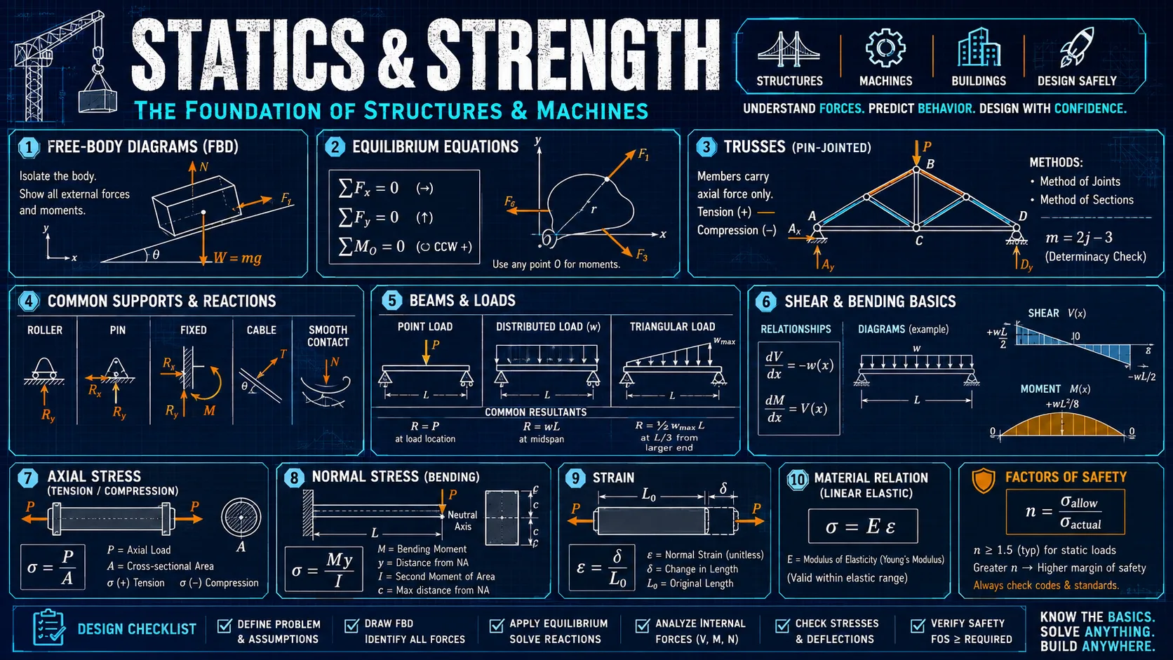
Statics and Strength of Materials Workbench
Sixteen modules covering free-body diagrams, support reactions, method of joints, section properties, shear and moment diagrams, bending and shear stress, axial load, torsion, thermal stress, principal stresses, combined loading, pressure vessels, factor of safety, and column buckling.
How this tool works
The modules follow the order a first solid-mechanics course does. Forces are resolved and a free body is checked for equilibrium, that equilibrium gives the support reactions, the internal shear and moment are traced along the member, and only then are those internal actions turned into stresses and checked against a failure criterion.
Section properties and the chosen material feed the later modules directly, so changing the flange thickness or switching from steel to aluminium propagates through the bending stress, the deflection estimate, and the buckling capacity without re-entering anything.
Each module opens with the question it answers, the governing relationship, and the specific thing worth noticing in the numbers, rather than presenting a bare calculator.
Core equations
R = √(ΣFx² + ΣFy²), θ = atan2(ΣFy, ΣFx)ȳ = ΣAȳ/ΣA, I = Σ(Ī + Ad²)dM/dx = V, so the moment peaks where the shear crosses zeroσ = My/I, τ = VQ/(It), δ = PL/AEτ = Tr/J, φ = TL/JG, J = π(do⁴ − di⁴)/32σ = −EαΔT for a fully restrained memberσ1,2 = (σx + σy)/2 ± √(((σx − σy)/2)² + τxy²)Pcr = π²EI/(KL)², σcr = π²E/(KL/r)²σhoop = pr/t and σlong = pr/2t for a thin-walled cylinderFoS = strength / applied stress, margin = FoS − 1Assumptions
- Linear-elastic, homogeneous, isotropic material behaviour below the yield point.
- Small deflections, so equilibrium is written on the undeformed geometry.
- Beams are prismatic and slender enough for Euler–Bernoulli theory, meaning plane sections stay plane and shear deformation is neglected.
- Bending is about a principal axis of the section, with no unsymmetric bending, torsion coupling, or lateral-torsional instability.
- Torsion applies to circular shafts only, where cross-sections do not warp.
- Loads are static. Fatigue, impact, and creep are outside the scope of these modules.
Limitations
- Beam analysis covers statically determinate members only: a simple span or a cantilever. Continuous and propped beams are statically indeterminate and need compatibility conditions this tool does not solve.
- Deflection uses the standard closed-form cases. For a load set that matches none of them the tool says so rather than returning a plausible wrong number.
- The truss module solves one pin joint with two unknown members, which is the teaching case. It does not assemble or solve a whole truss.
- Transverse shear stress is given for a solid rectangle. Flanged sections concentrate shear in the web and need the section-specific Q.
- Column capacity is the theoretical Euler and Johnson result with no imperfection, eccentricity, or code-based resistance factor. Real design values are lower.
- Pressure vessel results use the thin-wall formulas, with the Lamé thick-wall values shown alongside. Below r/t of about 10 the tool says the thin-wall figure is unreliable rather than presenting it as the answer.
- The ultimate strength offered in the factor-of-safety module is estimated at 1.5 times yield. Substitute the certified value before relying on it.
- Combined loading superposes axial, bending, and torsional stress at a surface point. It does not account for stress concentrations at holes, fillets, or keyways, which is often what actually governs.
- Nothing here is a substitute for a design code or for review by a licensed engineer.
References and verification
- Standard mechanics-of-materials formulationsThe relationships used are the conventional ones from an introductory solid-mechanics sequence: equilibrium, the parallel-axis theorem, Euler–Bernoulli beam theory, the elastic torsion formula, plane-stress transformation, and Euler buckling with the Johnson parabola for short columns.