Dynamics and Vibration Workbench
Eight modules covering rotational inertia, the mass-spring-damper in free and forced response, natural frequency, damping ratio from decay, shaft critical speed, two-plane rotor balancing, four-bar…
Engineering reference
Dynamics & Vibration: theory, method, and sources
This mechanical workspace publishes 7 governing equations, 5 stated assumptions, 6 documented boundaries, and 1 source so the numbers it returns can be checked rather than taken on trust.
How this tool works
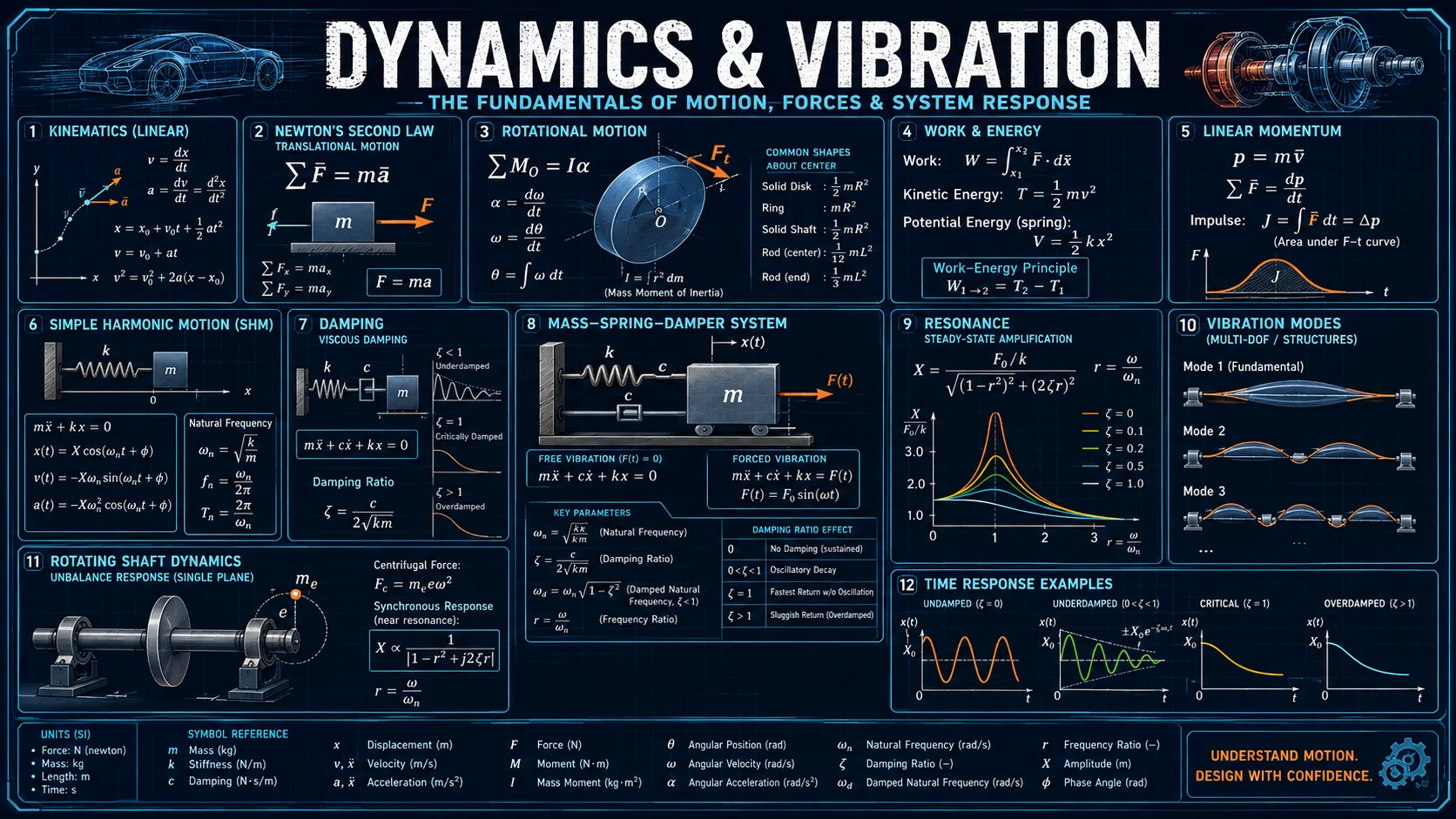
Every vibration module here is the same second-order system mẍ + cẋ + kx = F(t) seen from a different angle: natural frequency is its undamped root, damping ratio is measured from its decay, critical speed is where a rotor meets it, and the simulator shows the whole response.
The remaining modules cover how mass is distributed about an axis, how a rotor is corrected in two planes, and how a linkage or a projectile traces a path through space.
Each module opens with the question it answers, the governing relationship, and the specific thing worth noticing, rather than presenting a bare calculator.
Calculators and topics covered
- dynamics
- vibration
- resonance
- balancing
- linkages
- projectile motion
- rotational inertia parallel axis theorem
- mass spring damper simulator
- natural frequency calculator
- damping ratio logarithmic decrement
- shaft critical speed whirl
- two plane rotor balancing
- four bar linkage Grashof condition
- transmission angle linkage
Core equations
Method and assumptions
Assumptions
- Vibrating systems are linear, with viscous damping proportional to velocity and constant stiffness.
- Each system is idealised to a single degree of freedom, lumping mass at one point and neglecting the mass of the beam or shaft itself.
- Rotor balancing treats the shaft as rigid at the operating speed.
- The four-bar linkage has rigid links, ideal pin joints, and no clearance or friction.
- Projectile drag is linear in velocity, and there is no wind, spin, or lift.
Limitations and design boundaries
- Single-degree-of-freedom idealisations give only the first mode. A real distributed structure has an infinite set, and higher modes matter once the excitation is broadband.
- Coulomb, hysteretic, and squeeze-film damping are all non-viscous and do not fit the ζ model used here.
- Rigid-rotor balancing fails above roughly half the first critical speed, where the shaft itself deforms and flexible-rotor methods are needed.
- Linear drag suits small slow objects. A ball or a shell is closer to quadratic drag, where the force goes as v² and the asymmetry is stronger.
- The linkage solves position and velocity only; it does not compute accelerations, inertia forces, or the shaking force transmitted to the frame.
- Nothing here is a substitute for measurement, a design code, or review by a licensed engineer.
Sources and references
Primary sources are preferred for ratings, standards, manufacturer data, and externally defined constants.
- Standard dynamics and vibration formulationsThe relationships used are the conventional ones from an introductory dynamics and vibration sequence: the parallel-axis theorem, the damped second-order response, logarithmic decrement, Rayleigh and Dunkerley critical speed estimates, two-plane balancing, Grashof classification with the vector loop closure, and projectile motion under linear drag.