Loading tool…
Loading interactive tool…

Engineering reference

Theory, method, validation, and sources

The interactive workspace is paired with its published engineering context: core equations, assumptions, design boundaries, and source references. Worked examples, validation cases, and editorial review dates are displayed only where that supporting evidence has been published for the tool.

Calculations run locallyContent reviewed August 10, 2026Calculation & source methodology

How this tool works

Model common geared transmissions and compare how tooth counts affect output speed, direction, torque multiplication, and pitch-line velocity.

Switch between single external meshes, multi-stage compound trains, internal ring-and-pinion meshes, and planetary gearsets with selectable input and fixed members.

Animated diagrams help connect the kinematic relationships to the geometry actually transmitting the motion.

Engineering theory

Gear trains trade speed for torque according to tooth-count ratio

In an ideal external mesh, equal tangential pitch-line velocity at the point of contact means angular speed scales inversely with pitch diameter and thus inversely with tooth count when the module is shared. A larger driven gear therefore rotates more slowly and carries proportionally more torque than the smaller driver.

An external mesh reverses rotation direction, whereas an internal mesh keeps the same direction. Compound trains multiply ratios stage-by-stage, and idlers change direction or centre distance without changing the net ratio.

Planetary gearsets are governed by relative motion, not a simple one-line ratio

A planetary set has three principal members: the sun, the ring, and the carrier. The Willis equation relates their speeds through the tooth-count ratio Nr/Ns. Once any one member is fixed and another is driven, the third member speed follows directly.

Because one member can rotate while carrying the planet axes, a planetary train can produce reductions, overdrives, or reversals depending on which member is grounded and which member is used as the output.

Inputs and outputs explained

Inputs

Tooth counts

Numbers of teeth on driver, driven, sun, ring, and planet gears according to the chosen mode.

Input speedrpm

Angular speed of the driven member.

Input torqueN·m

Torque applied to the input member.

Modulemm

Metric gear module for the schematic geometry calculations.

Efficiency

Scalar transmission efficiency used for preliminary output-power/torque estimates.

Outputs

Speed ratio

Relative speed ratio between input and output members.

Output speedrpm

Predicted output angular speed.

Output torqueN·m

Predicted output torque after the user-entered efficiency is applied.

Pitch-line velocitym/s

Circumferential velocity at the pitch circle.

Tangential tooth forceN

Estimated transmitted pitch-circle force from torque and pitch diameter.

Calculators and topics covered

  • gear train
  • planetary gear
  • compound gear train
  • internal gear
  • speed ratio
  • torque
  • machine design
  • free gear train simulator
  • online planetary gear calculator
  • gear ratio simulator
  • ring gear
  • epicyclic gear
  • spur gear motion
  • mechanical transmission

Core equations

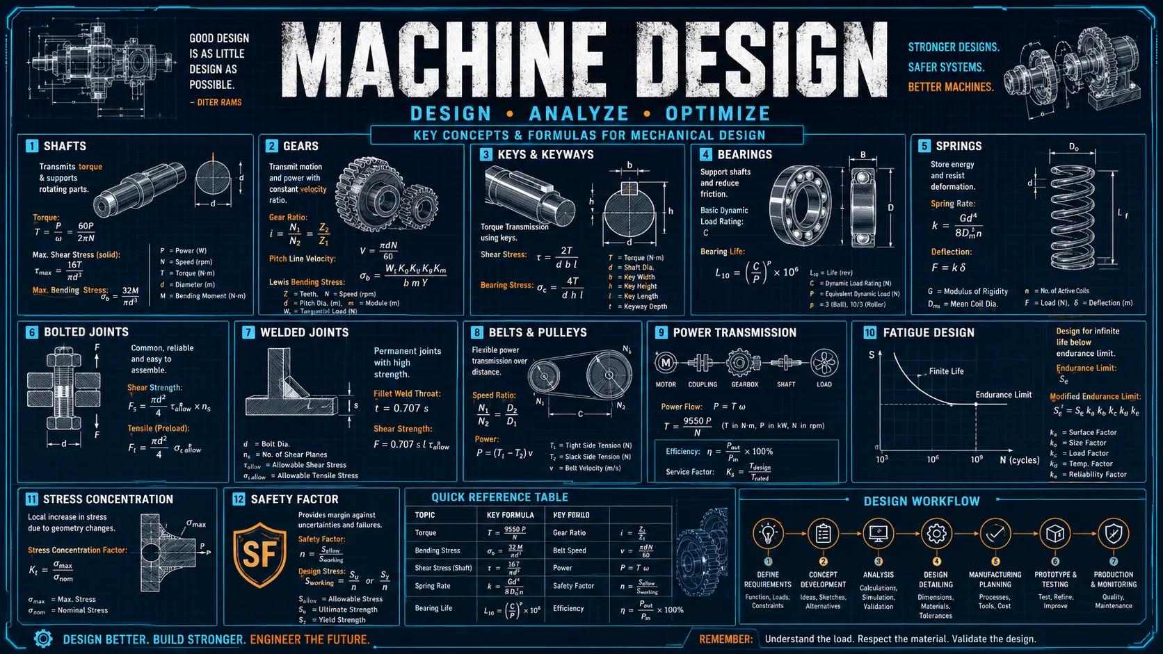
i = N_driven / N_driverω_out = ω_in / iT_out ≈ T_in · i · η(ω_s − ω_c)/(ω_r − ω_c) = −N_r / N_sv_pitch = ωrd = mN

Worked examples

Simple 4:1 reduction

An 18-tooth pinion drives a 72-tooth gear at 1750 rpm.

Inputs
  • Driver = 18 teeth
  • Driven = 72 teeth
  • Input speed = 1750 rpm
  • Efficiency ≈ 0.97

Result: The ratio is 4, the output speed is about 437.5 rpm, and the output torque is roughly four times the input torque after losses.

Interpretation: A larger driven gear slows the rotation while multiplying torque.

Planetary reduction with ring fixed

A 24-tooth sun drives a 72-tooth ring set with the ring fixed and the carrier as output.

Result: The carrier runs at one quarter of the sun speed because 1 + Nr/Ns = 4.

Interpretation: Holding the ring produces a compact reduction gearset with coaxial input and output.

Common mistakes

Confusing driven/driver when reading the ratio

Switching the numerator changes a reduction into an overdrive.

Better approach: Use driven teeth over driver teeth for the simple ratio in this simulator.

Assuming idlers change the ratio

Idlers change centre distance and direction, not net ratio.

Better approach: Only gear pairs that change tooth-count ratio alter the total ratio product.

Using arbitrary sun/ring/planet tooth counts in a simple planetary set

A concentric basic planetary set requires the ring tooth count to match the sun and planet geometry.

Better approach: Use Nr = Ns + 2Np as the baseline simple-geometry consistency condition.

Method and assumptions

For ordinary and internal meshes, calculate the tooth-count ratio and infer output speed from equal pitch-line velocity.

For compound trains, multiply stage ratios and propagate speed/torque stage-by-stage.

For planetary trains, use the Willis relationship between sun, ring, and carrier speeds after selecting the fixed and input members.

Render a schematic animation whose rotation rate is proportional to the calculated speeds.

Assumptions

  • The simulator uses rigid gears with ideal involute-like pitch relationships and does not model tooth deflection, backlash, or impact.
  • Efficiency is represented by a simple scalar entered by the user. Losses are not load, speed, temperature, lubrication, or duty dependent.
  • The simple planetary mode assumes a concentric single-stage sun-planet-ring set and uses the classic Willis relationship for kinematics.
Limitations and design boundaries

  • This tool is for kinematics, preliminary sizing, and conceptual understanding. It is not an AGMA stress calculator, a gearbox thermal model, or a bearing/shaft life tool.
  • Tooth profile generation, undercut avoidance, contact stress, root bending stress, lubrication regime, backlash, dynamic factors, and manufacturing tolerances are outside the current model.
  • The animation is schematic and not a CAD-accurate representation of tooth form or clearances.

Validation cases

These checks document how representative calculations are cross-checked against analytic or reference results.

Validation policy

External mesh ratio check

Analytic cross-check
Method
18-tooth pinion driving a 72-tooth gear.
Expected
Ratio = 4 and output speed = input/4.

Internal mesh direction check

Analytic cross-check
Method
Pinion driving an internal ring gear.
Expected
Output rotates in the same direction as the pinion.

Planetary reduction check

Analytic cross-check
Method
Ring fixed, sun input, carrier output.
Expected
ωc = ωs/(1 + Nr/Ns).

Sources and references

Primary sources are preferred for ratings, standards, manufacturer data, and externally defined constants.

Source policy
  • Shigley — Mechanical Engineering DesignIntroductory and intermediate gear-geometry, train-ratio, and machine-design relationships.
  • Norton — Machine DesignGear trains, gear geometry, and practical transmission design.
  • AGMA introductory referencesDesign context for gears, loads, and geometry beyond the simple kinematic model.

Related concepts