Loading tool…
Loading interactive tool…

How this tool works

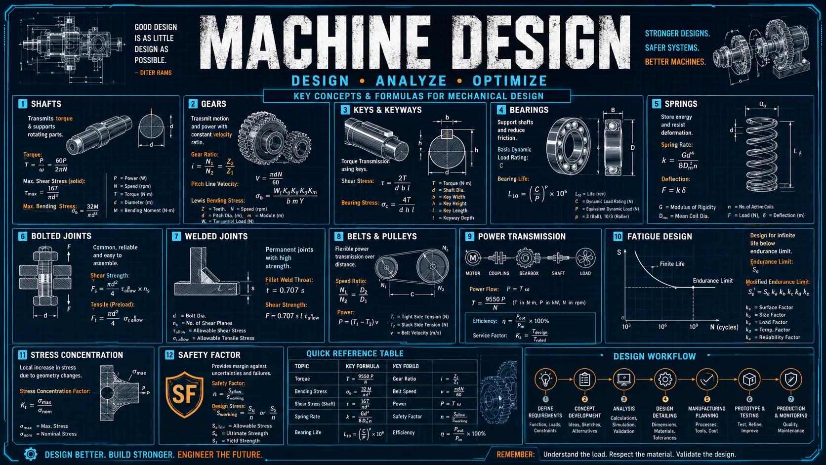
The modules follow a power path through a machine: the source turns, gears or a belt or chain change the speed and torque, bearings and shafts carry the result, and keys, bolts, and threads hold it all together.

Springs, flywheels, cams, the classical machines, and hydraulic actuators cover the remaining ways a design stores, smooths, shapes, or amplifies that motion.

Each module opens with the question it answers, the governing relationship, and the specific thing worth noticing, rather than presenting a bare calculator.

Core equations

Ratio = N_driven / N_driver; torque multiplies as speed dividesd = m·N, base circle = d·cos φ, addendum = m, dedendum = 1.25mT1/T2 = e^(μθ) for a flat belt, μ/sin(β/2) for a V-beltSprocket pitch diameter = p / sin(π/N)L10 = (C/P)^p million revolutions, p = 3 balls, 10/3 rollersd = [16√(M² + T²) / (π·τallow)]^(1/3)τ = Kw·8FD/(πd³), k = Gd⁴/(8D³Na)ΔE = I·ω̄²·CsForce = pressure × area; annulus = bore − rod

Assumptions

  • Steady-state operation at the stated speed and load, with no shock or start-up transient.
  • Gears are standard full-depth involute profiles running at their theoretical centre distance.
  • Belt and chain calculations assume an open drive on parallel shafts with no slip beyond the friction limit.
  • Bearing life uses catalogue dynamic capacity with adequate lubrication and correct mounting.
  • Shaft, key, and bolt checks are static strength calculations against yield.

Limitations

  • Shaft sizing is a static check. A rotating shaft under steady bending sees fully reversed stress each revolution and needs a fatigue analysis with stress concentration factors at every shoulder, keyway, and groove.
  • Gear teeth are proportioned geometrically only. Tooth bending and pitting capacity need the Lewis and Hertzian checks with the full set of AGMA derating factors.
  • The bolt torque relation uses a nut factor that scatters by roughly ±25 % in practice, so torque control alone cannot deliver accurate preload. Critical joints are tightened by angle or by measured bolt stretch.
  • Bearing L10 is a fatigue statistic. It does not predict failure from lubrication breakdown, contamination, or misalignment, which cause most bearings to fail in service.
  • Cam profiles cover the rise only, with no dwell or return, and the follower is assumed rigid with no jump at speed.
  • Nothing here is a substitute for a design code, a manufacturer catalogue, or review by a licensed engineer.

References and verification

  • Standard machine design formulationsThe relationships used are the conventional ones from an introductory machine-design sequence: involute gear proportions, the capstan belt equation, ISO tensile stress area, the basic bearing rating life, the Wahl correction for helical springs, and the standard cam motion curves.