Browser-local interactive workspace
Interactive workspace initializes in your browser. Engineering method, assumptions, validation, and references are available below.

Engineering reference

Component Library & Design: theory, method, and sources

This electrical engineering workspace publishes 5 governing equations, 4 stated assumptions, 2 documented boundaries, 2 worked examples, 2 validation cases, and 3 sources so the numbers it returns can be checked rather than taken on trust.

Calculations run locallyContent reviewed August 9, 2026Calculation & source methodology

How this tool works

A component-first library covers major passive, semiconductor, analog, power, digital, interface, computing/data-conversion, sensor, protection, electromechanical, connector, and timing families.

Each component guide explains operating behavior, how to use the part, variants, critical datasheet fields, selection checks, common mistakes, packages, and representative applications.

A curated real-part selector adds manufacturer-linked records, datasheet summaries, search/filtering, up-to-four-part comparison, and direct handoff into supported design calculators.

Eleven live design tools connect datasheet parameters to first-pass LED, BJT, MOSFET, gate-driver, loaded-divider, RC, LDO, op-amp, regulator-selection, ADC front-end, and TVS transient-protection calculations.

Six guided circuit workflows combine real component records with editable operating conditions, pass/warn/fail compatibility checks, first-pass metrics, small BOMs, functional signal/power-path diagrams, and handoff into the detailed calculators.

An interactive functional circuit builder adds draggable blocks, drag-to-wire power/logic/analog/motor/bus connections, explicit 0 V references, loaded resistor-divider and LED-resistor branches, configurable resistor/capacitor/diode/TVS/fuse elements, named nets with branch-current visualization, parallel downstream current budgeting, improved regulator input-demand estimates, automatic sizing recommendations, aggregated BOMs, live compatibility warnings, reusable system templates, and functional netlist export.

A bounded signal lab adds DC/sine/square/triangle/sawtooth/pulse generation, PWM/clock logic sources, first-order RC/RL low-pass and high-pass transient response, curated op-amp GBW/slew/output clipping, CH A-D scope probes, edge triggering, automatic Vpp/RMS/average/frequency/duty measurements, and waveform CSV export.

An instrument layer adds D0-D7 logic-analyzer probes with adjustable thresholds, logic-analyzer CSV export, differential virtual multimeters, frequency counters, UART TX generation plus configurable 7/8-bit parity/stop-bit decoding, browser-local project snapshots, and portable Circuit Builder JSON projects for moving designs between computers.

The previous drill-down semiconductor, op-amp, logic, package, measurement, marking, preferred-value, and equation references remain available alongside the new component library.

Engineering theory

A datasheet is a set of operating boundaries, not a single headline rating

Component selection starts by separating absolute maximum ratings from recommended operating conditions and characterized performance. A device can survive a stated maximum without being specified to operate correctly there.

The Component Library therefore emphasizes the conditions attached to values such as MOSFET RDS(on), op-amp output swing, regulator dropout, ADC input range, and thermal resistance rather than comparing parts by one headline number.

Circuit behavior depends on the operating point and surrounding components

A MOSFET, op amp, regulator, ADC, or protection part cannot be evaluated independently of supply voltage, load current, source impedance, switching frequency, thermal path, and the passive network around it. The design calculators and circuit workflows combine those conditions with curated component data to expose first-order compatibility problems.

The interactive builder propagates supported power and signal values through functional connections, but it deliberately does not claim to be a full SPICE or PCB-level simulator.

DC checks and waveform simulation answer different questions

DC analysis is useful for rail voltage, current budgeting, conduction loss, resistor dissipation, regulator loading, and static protection checks. Time-domain simulation is needed for RC/RL response, PWM, clocks, UART, op-amp slew/GBW limits, and oscilloscope-style measurements.

The workbench keeps these models explicit so a steady-state power result is not accidentally presented as a transient, stability, EMI, or fault-current result.

Inputs and outputs explained

Inputs

Component family or real part

Selects the generic design model and, where available, manufacturer-backed engineering profile used by compatibility checks.

Operating voltages and currentsV / A

Defines the actual application conditions rather than relying on device headline ratings.

Thermal conditions°C / °C/W

Ambient temperature and effective thermal resistance used by first-order junction-temperature estimates.

Passive valuesΩ / F / H

Resistor, capacitor, and inductor values used by static and transient calculations.

Signal parameters

Waveform, amplitude, offset, frequency, duty cycle, phase, baud rate, or sample/acquisition settings used by signal-domain tools.

Circuit topology

Typed power, logic, analog, motor, and bus connections determine which checks and propagation rules are valid.

Outputs

Compatibility checks

Pass, warning, fail, and engineering-note results for supported component and connection constraints.

Loss and thermal estimatesW / °C

First-order device dissipation, temperature rise, and junction-temperature estimates.

Rail/current budgetV / A / W

Supported DC power paths, branch demand, regulator utilization, and element loss.

BOM

Aggregated component list generated from supported real parts and configurable passives/protection elements.

Waveforms and measurements

Oscilloscope, logic-analyzer, DMM, counter, and protocol-decoder outputs from supported signal paths.

Calculators and topics covered

  • electronics component library
  • real electronic parts
  • datasheet comparison
  • reference circuits
  • interactive circuit builder
  • virtual oscilloscope
  • logic analyzer
  • virtual multimeter
  • frequency counter
  • PWM generator
  • signal generator
  • RC transient simulator
  • RL transient simulator
  • parallel current analysis

Core equations

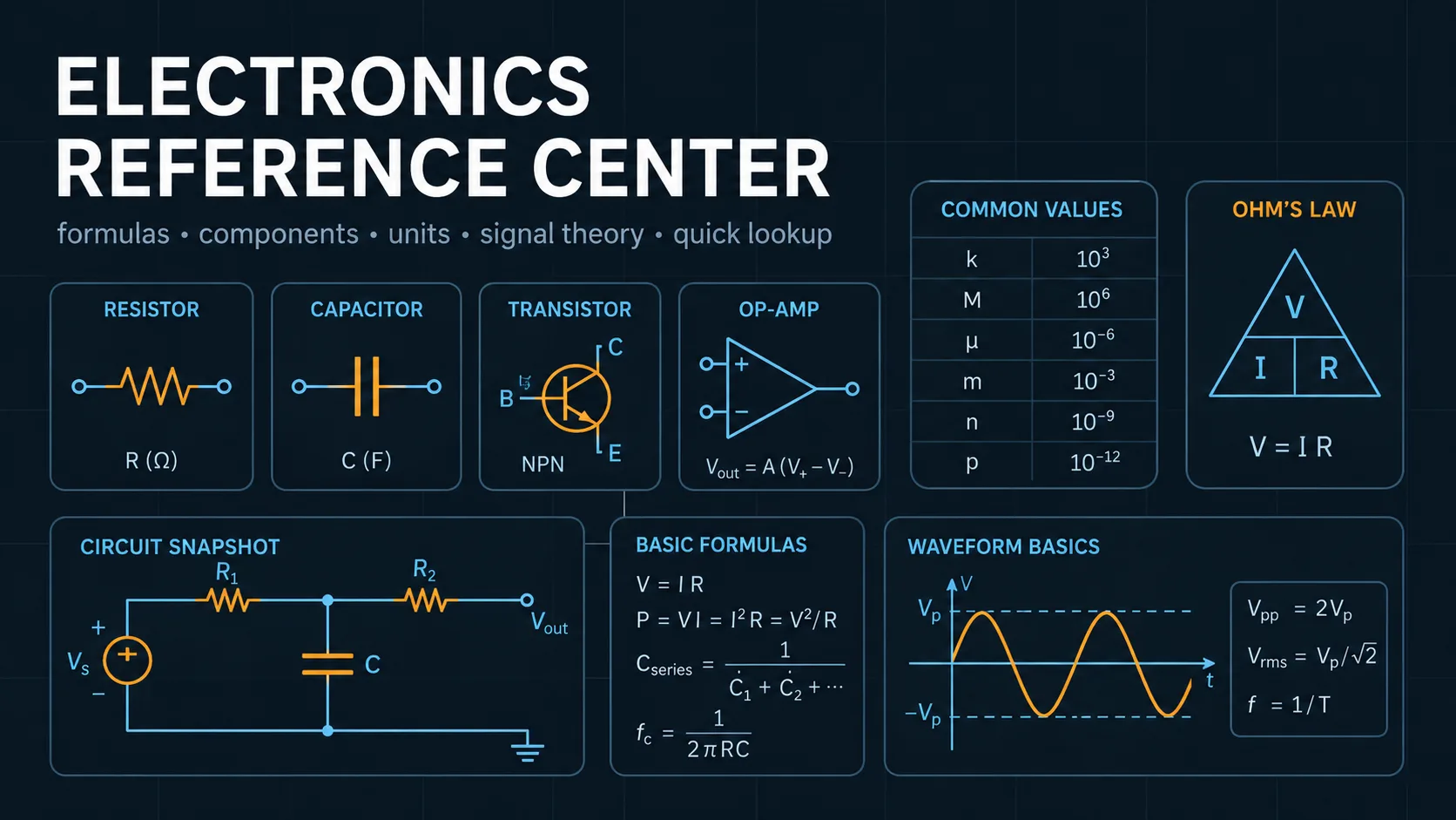
tr0.35BWtr \approx \frac{0.35}{\mathrm{BW}}fc=12πRCfc = \frac{1}{2 \pi RC}SNRADC6.02N+1.76  dBSNRADC \approx 6.02 N + 1.76\; \mathrm{dB}Tj=Ta+PθTj = Ta + P\sum \theta Pcond=IRMS2RDS(on)Pcond = I_{\mathrm{RMS}}^{2} R_{DS} \left(on\right)

Worked examples

Why a 3.3 V GPIO can be questionable for an IRLZ44N

An ESP32-class 3.3 V logic output drives an IRLZ44N gate in the low-side switch workflow.

Inputs
  • 3.3 V gate drive
  • IRLZ44N selected from the curated part library
  • load current and bus voltage entered by the user
Method
  1. The workflow compares gate-drive voltage with the datasheet conditions attached to the curated RDS(on) values.
  2. The lowest curated RDS(on) characterization point is above 3.3 V, so the design cannot assume the low resistance quoted at higher gate voltage.

Result: The workflow issues a gate-drive warning instead of marking the MOSFET as fully characterized at 3.3 V.

Interpretation: VGS(th) is not the gate voltage that guarantees low RDS(on). Use a device characterized at the actual drive voltage or add an appropriate gate driver.

RC low-pass transient

A 1 kΩ resistor and 100 nF capacitor form a first-order low-pass stage driven by a square wave.

Inputs
  • R = 1 kΩ
  • C = 100 nF
Method
  1. Compute τ = RC.
  2. Compute fc = 1/(2πRC).
  3. Numerically step the first-order capacitor response for the oscilloscope trace.

Result: τ = 100 µs and fc ≈ 1.592 kHz.

Interpretation: Signals near or above the cutoff are attenuated and rounded because the capacitor cannot follow the input instantaneously.

Common mistakes

Designing from absolute maximum ratings

Absolute maximum values describe survival boundaries, not normal operating targets or guaranteed performance.

Better approach: Design inside recommended conditions and use the electrical-characteristics tables and curves at the actual operating point.

Using MOSFET threshold voltage as a logic-level specification

VGS(th) is measured at very small drain current and does not guarantee low channel resistance.

Better approach: Check RDS(on) at a gate voltage equal to or below the actual driver voltage and evaluate switching/thermal losses separately.

Assuming the browser model replaces bench validation

First-order models cannot capture every parasitic, tolerance, thermal path, layout effect, transient, or failure mode.

Better approach: Use the workbench to size and understand the design, then confirm critical behavior with manufacturer models, simulation, and hardware measurements.

Method and assumptions

Generic component guides explain the parameter relationships first. Curated real-part records then add compact engineering profiles sourced from manufacturer documentation so calculators and workflows can preload known values without pretending to reproduce an entire distributor database.

The circuit builder uses bounded, first-order models for topologies it explicitly supports. Unsupported analog loops, switching parasitics, SOA transients, EMI/EMC, PCB thermal effects, creepage/clearance, and regulatory coordination are surfaced as design boundaries rather than silently approximated.

Assumptions

  • E6, E12, and E24 use their standard nominal values; denser E-series are generated as rounded logarithmic preferred-number approximations.
  • Marking decoders cover common code formats, not every manufacturer convention.
  • Reference entries summarize broadly applicable engineering concepts rather than reproducing a specific device datasheet.
  • Curated real-part values and structured engineering profiles are compact snapshots of primary manufacturer documentation and must be rechecked against the linked current datasheet before a final design.
Limitations and design boundaries

  • Always verify the exact component datasheet, package drawing, pin assignment, absolute maximum ratings, recommended operating conditions, tolerance, safety category, and measurement-equipment manual.
  • Reference examples are educational first-pass analyses and do not replace simulation, laboratory validation, safety review, grounding/return-current analysis, fault-current coordination, or regulatory design work.

Validation cases

These checks document how representative calculations are cross-checked against analytic or reference results.

Validation policy

E24 preferred value identity

Verified result
Method
Request the preferred E24 value for a 4.7 kΩ target.
Expected
4.7 kΩ is already an E24 nominal value and should be returned unchanged.
Observed
The preferred-value engine returns 4.7 kΩ with the selected unit.
Tolerance
Exact nominal value.

RC time constant and cutoff

Analytic cross-check
Method
Cross-check R = 1 kΩ and C = 100 nF using τ = RC and fc = 1/(2πRC).
Expected
τ = 100 µs and fc ≈ 1.59155 kHz.
Observed
The RC design engine and transient model use the same first-order relationships.
Tolerance
Floating-point rounding only for the analytic values.

Sources and references

Primary sources are preferred for ratings, standards, manufacturer data, and externally defined constants.

Source policy
  • IEC 60063 preferred number seriesPreferred resistor and capacitor value series.
  • Manufacturer datasheets and application notesPrimary source for component ratings, curves, pinouts, package dimensions, land patterns, and recommended use.
  • Instrument and probe manualsPrimary source for grounding, input limits, bandwidth, category ratings, and safe measurement practice.

Related concepts